Section 5: Traffic Inspection
5.1 Test Spoke-to-Internet Connectivity
In this test, traffic flows from a spoke VPC through AWS Transit Gateway and FortiGate to the Internet.
The expected traffic path is:
Spoke 1 VM → AWS Transit Gateway → FortiGate → InternetConnect to the Spoke 1 VM
In the AWS Management Console, confirm that the selected Region is Frankfurt (
eu-central-1).Open the Amazon EC2 console.
Select Instances.
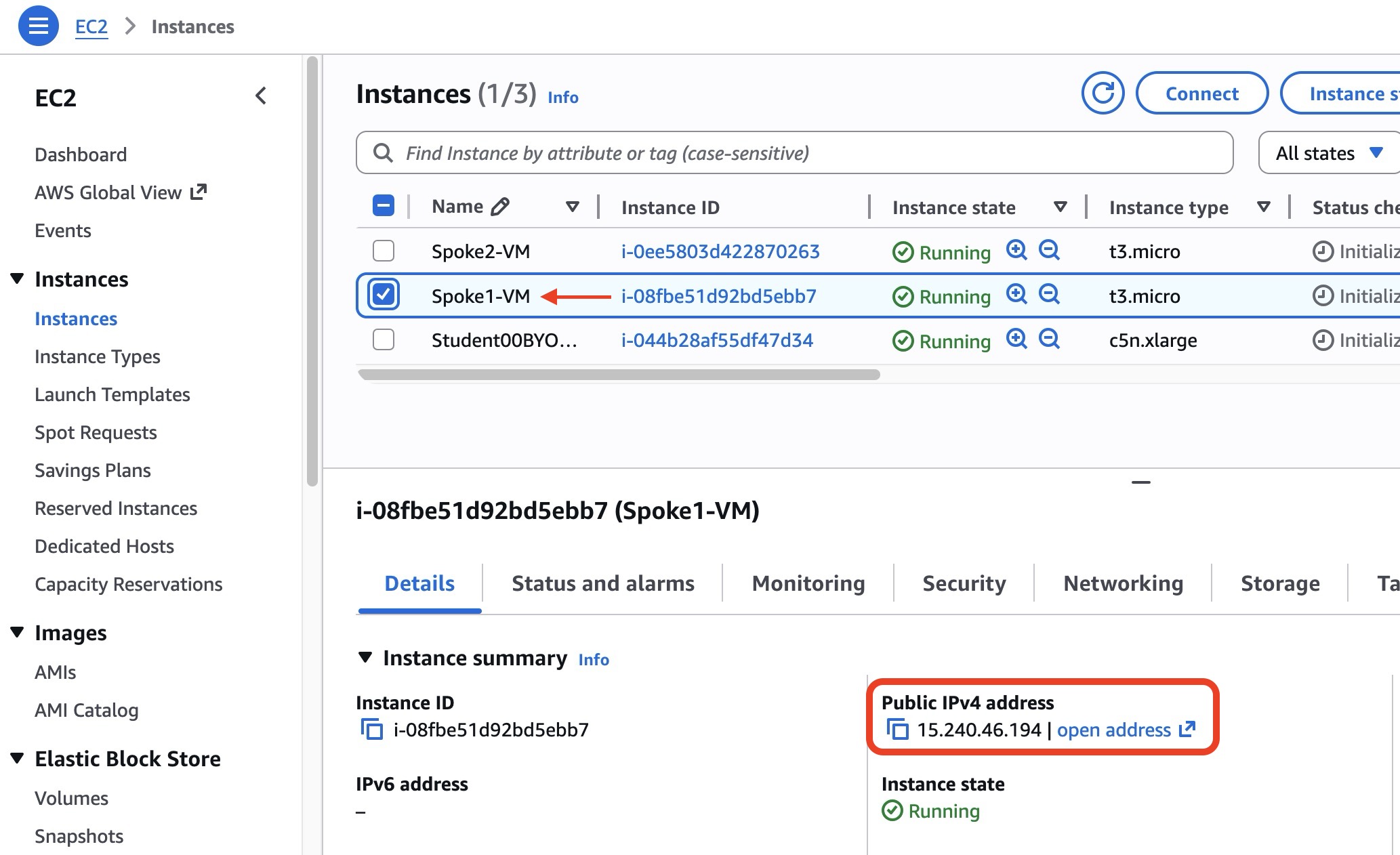
Locate
Spoke1-VM.Record its public IPv4 address.
Open a terminal on your computer.
Change to the directory containing the private key created in Section 1.
Connect to
Spoke1-VMusing SSH:bashssh -i Student01-key.pem ubuntu@<SPOKE1_PUBLIC_IP>Replace:
Student01-key.pemwith the name of your private key file.<SPOKE1_PUBLIC_IP>with the public IPv4 address ofSpoke1-VM.
TIP
The default username for the Ubuntu instance is:
ubuntuIf you are using macOS or Linux and receive a private-key permissions error, run:
chmod 400 Student01-key.pemThen retry the SSH connection.
Test Internet Connectivity
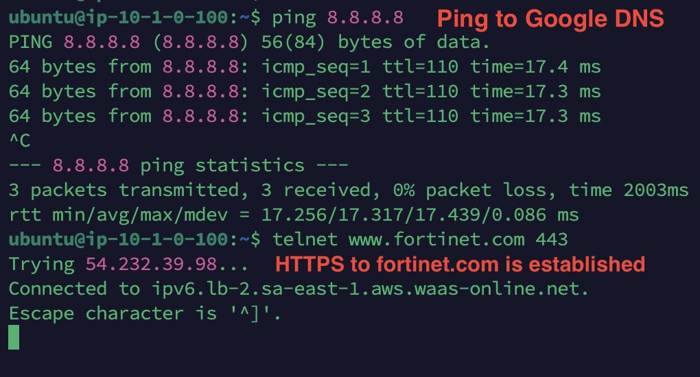
From the SSH session, test ICMP connectivity through FortiGate:
bashping -c 4 8.8.8.8Confirm that replies are received.
Test HTTPS connectivity to the Fortinet website:
curl -I https://www.fortinet.comA successful test should return an HTTP response header.
If telnet is installed, you may also test TCP port 443:
telnet www.fortinet.com 443INFO
The spoke instances use a wait-for-FortiGate script.
Their setup completes only after they can successfully reach the Internet through FortiGate.
Verify the Egress Traffic Logs
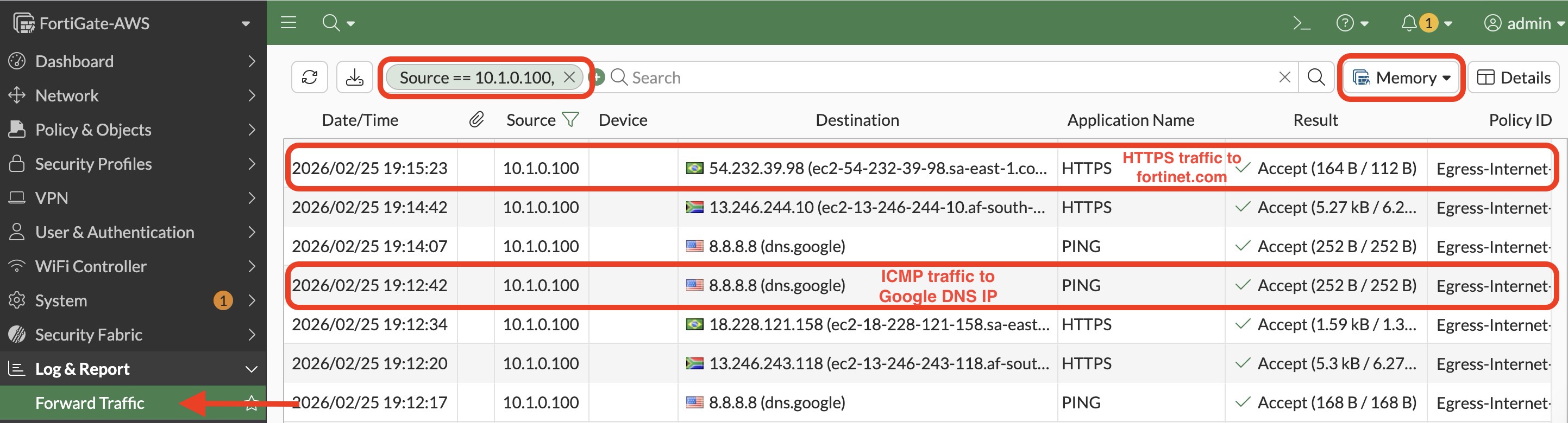
In the FortiGate GUI, go to:
Log & Report > Forward Traffic
Locate traffic originating from the spoke networks:
text10.1.0.0/16 10.2.0.0/16Confirm that the preconfigured Internet-access policy processed the traffic.
Verify that the traffic action is Accept.
TIP
If the traffic does not appear immediately, wait a few seconds and refresh the log view.
5.2 Test Spoke-to-Spoke Connectivity
In this test, traffic flows from Spoke 1 to Spoke 2 through AWS Transit Gateway and FortiGate.
The expected traffic path is:
Spoke 1 VM → AWS Transit Gateway → FortiGate → AWS Transit Gateway → Spoke 2 VMCreate the East-West Firewall Policy
In the FortiGate GUI, go to:
Policy & Objects > Firewall Policy
Select Create New.
Create a firewall policy that permits traffic from the Spoke 1 network to the Spoke 2 network.
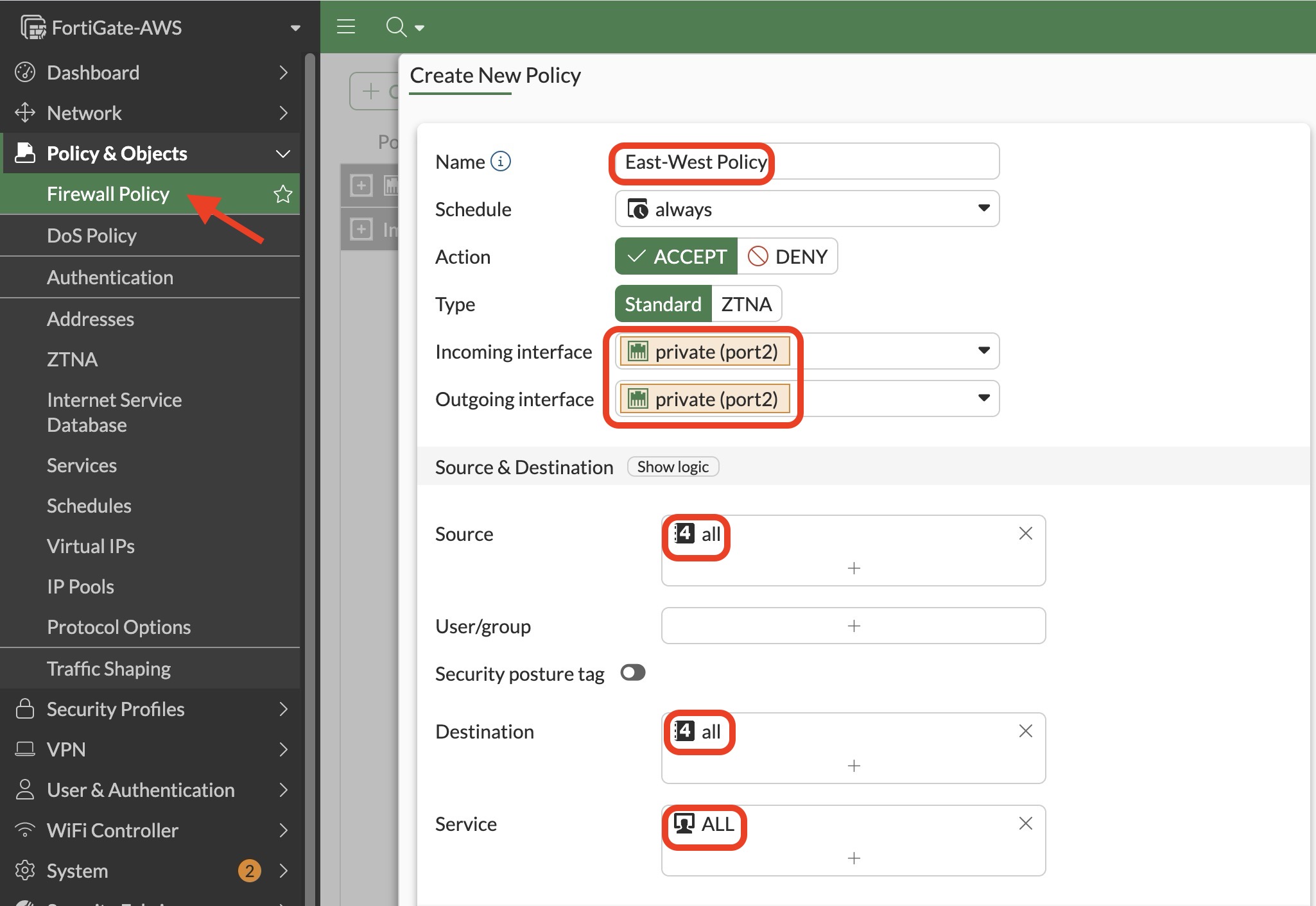
Configure the policy as shown in the lab screenshot.
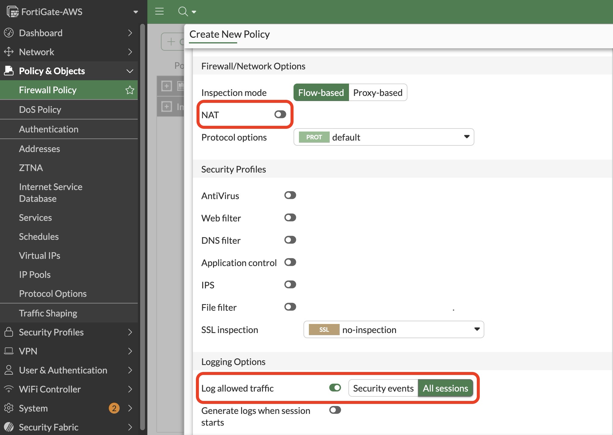
Use a descriptive policy name, such as:
textSpoke1-to-Spoke2Confirm that the policy:
- Uses the interface associated with the AWS Transit Gateway traffic path.
- Permits traffic from the Spoke 1 network.
- Permits traffic to the Spoke 2 network.
- Allows the required services.
- Has logging enabled.
- Is enabled.
INFO
Network Address Translation is normally not required for traffic between the spoke networks because both networks use private AWS addresses.
WARNING
Place the new policy above any broader deny policy that could block the spoke-to-spoke traffic.
Generate East-West Traffic
Return to the SSH session connected to
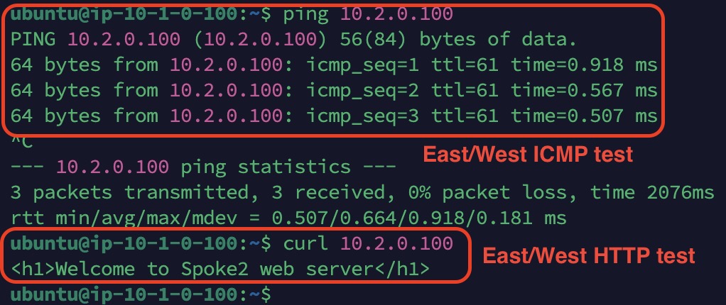
Spoke1-VM.Test ICMP connectivity to the Spoke 2 web server:
bashping -c 4 10.2.0.100Test HTTP connectivity to the Spoke 2 web server:
bashcurl http://10.2.0.100Confirm that the command returns content from the Spoke 2 web server.
Verify the East-West Traffic Logs
In the FortiGate GUI, go to:
Log & Report > Forward Traffic
Locate traffic with:
- A source address from the Spoke 1 network
- Destination address
10.2.0.100 - The east-west firewall policy created earlier
Confirm that the policy processed and accepted the traffic.

5.3 Test Internet-to-Spoke Connectivity
In this test, FortiGate virtual IP objects publish the spoke web servers to the Internet.
The expected traffic paths are:
Internet → FortiGate TCP port 8081 → Spoke 1 web server TCP port 80Internet → FortiGate TCP port 8082 → Spoke 2 web server TCP port 80Create the Virtual IP Objects
Create two virtual IP objects using the following values:
| Spoke | External TCP port | Internal web server |
|---|---|---|
| Spoke 1 | 8081 | 10.1.0.100:80 |
| Spoke 2 | 8082 | 10.2.0.100:80 |
In the FortiGate GUI, go to:
Policy & Objects > Virtual IPs
Select Create New > Virtual IP.
Create the virtual IP object for Spoke 1.
Configure port forwarding from external TCP port
8081to:text10.1.0.100:80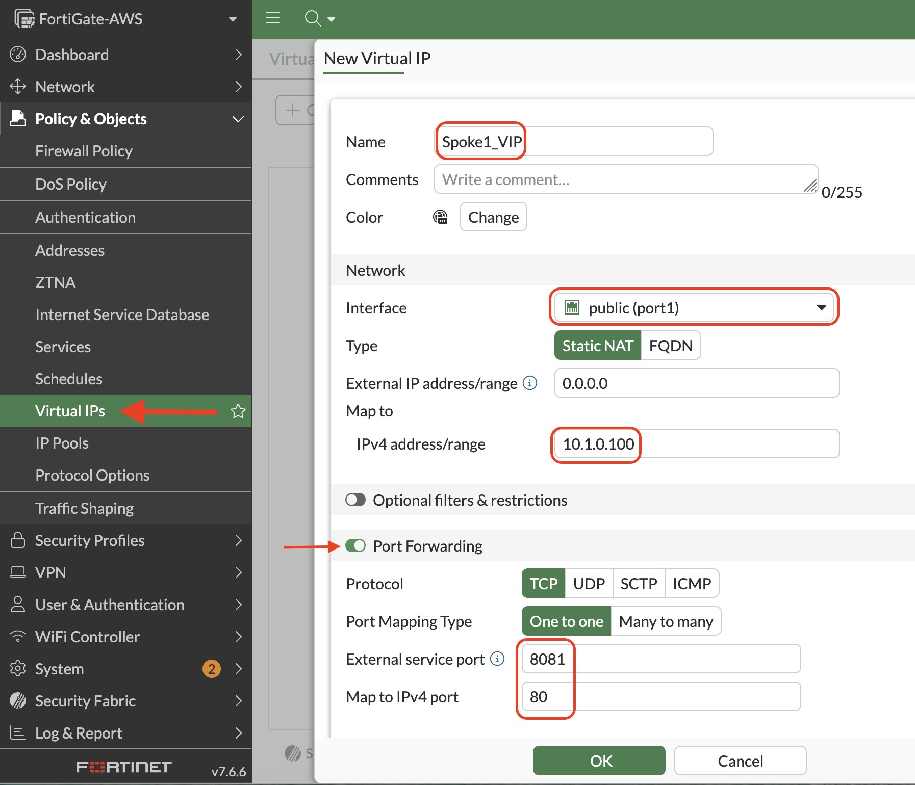
Create the virtual IP object for Spoke 2.
Configure port forwarding from external TCP port
8082to:text10.2.0.100:80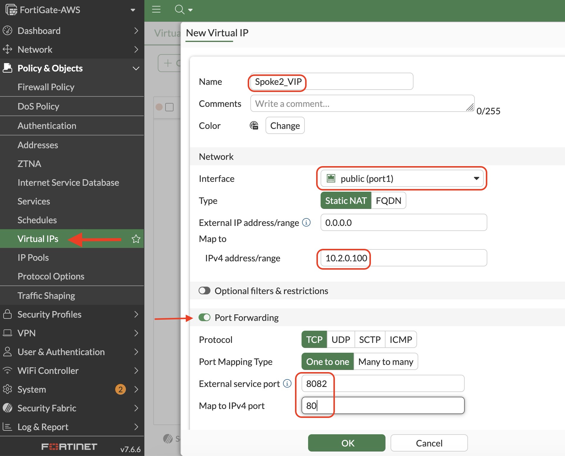
WARNING
Use the FortiGate WAN interface as shown in the screenshots.
Do not use the public IP addresses of the spoke VMs for these virtual IP objects.
5.4 Create the Ingress Firewall Policy
In the FortiGate GUI, go to:
Policy & Objects > Firewall Policy
Select Create New.
Create a firewall policy that permits inbound HTTP traffic from the WAN interface to the two virtual IP objects.
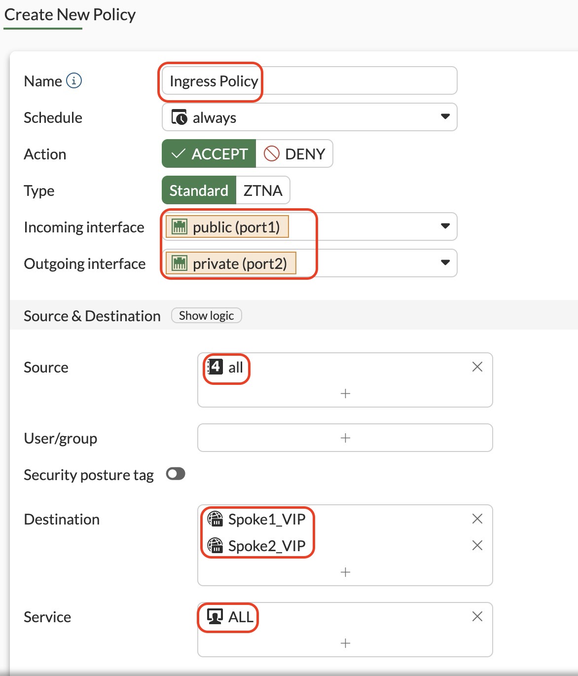
Configure the policy as shown in the lab screenshot.
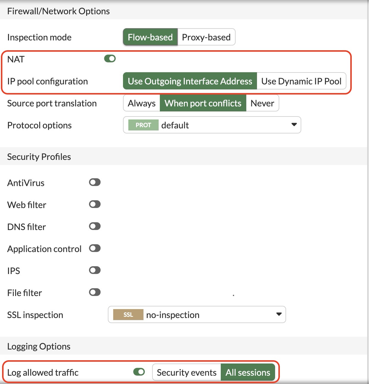
Confirm that the policy:
- Uses the FortiGate WAN interface as the incoming interface.
- Uses the interface associated with the spoke traffic path as the outgoing interface.
- Uses the two virtual IP objects as destinations.
- Permits TCP traffic to the mapped services.
- Has logging enabled.
- Is enabled.
INFO
The virtual IP objects perform destination NAT from FortiGate TCP ports 8081 and 8082 to TCP port 80 on the internal web servers.
5.5 Test the Published Web Services
In the Amazon EC2 console, locate the public IPv4 address of the FortiGate instance.
Open the following URL in a web browser to access the Spoke 1 web server:
texthttp://<FORTIGATE_PUBLIC_IP>:8081Replace
<FORTIGATE_PUBLIC_IP>with the public IPv4 address of the FortiGate instance.Confirm that the Spoke 1 web page is displayed.

Open the following URL to access the Spoke 2 web server:
texthttp://<FORTIGATE_PUBLIC_IP>:8082Confirm that the Spoke 2 web page is displayed.

WARNING
These tests use HTTP rather than HTTPS because the internal Ubuntu web servers listen on TCP port 80.
5.6 Verify the Ingress Traffic Logs
In the FortiGate GUI, go to:
Log & Report > Forward Traffic
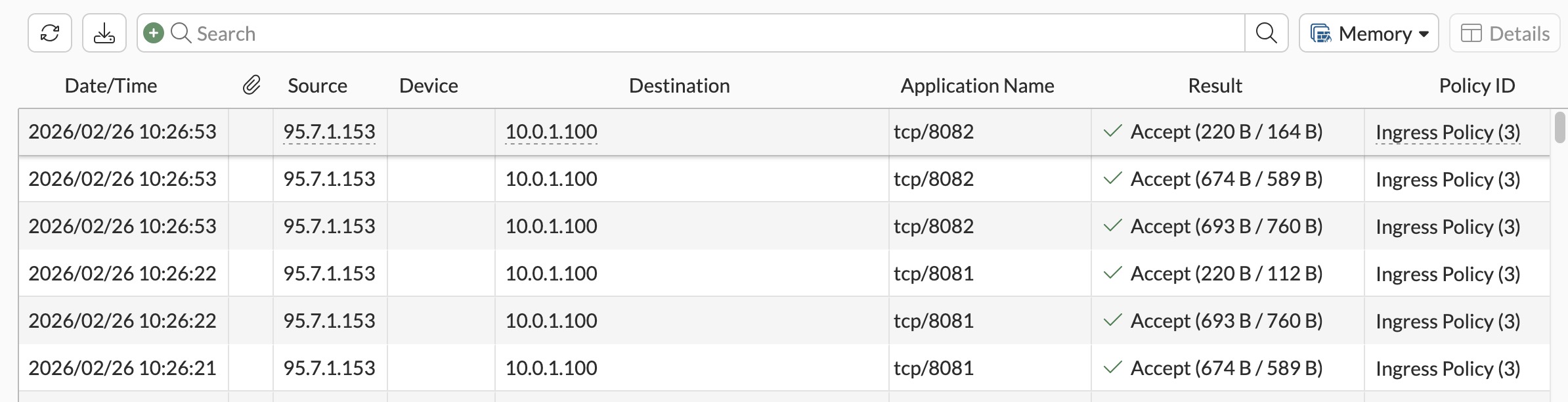
Locate the sessions for external TCP ports:
text8081 8082Confirm that the ingress firewall policy processed and accepted the traffic.
Verify that the translated destination addresses correspond to:
text10.1.0.100 10.2.0.100
Next Step
Continue to Section 6: Resource Cleanup.